Molybdenum Wire And EDM Gel Are The Guarantee of Surface Finish for Ultra-high Thickness Cutting
by
ZhangRay
25 Feb 2022
PRODUCTS USED IN THIS TEST:
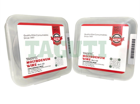
- EDM MOlybdenum Wire φ0.22mm (TAGUTI Brand)
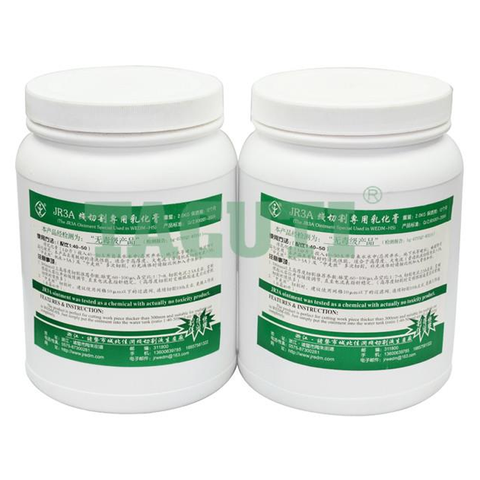
- JR-3A EDM Gel
Ultra-high thickness cutting is the advantage of high-speed WEDM. At present, it is not very difficult to cut ultra-high thickness (>1000mm) workpieces. The difficulty lies in how to stably cut for a long time and ensure the finish of the cutting surface of the workpiece. This test uses the upgraded JR-3A EDM Gel and the TAGUTI brand EDM Molybdenum Wire with characteristics of high purity, high strength and low elongation, which started in 1997.
1. Reasons for poor surface finish
During the ultra-high thickness cutting, the rigidity of the molybdenum wire decreases due to the substantial increase in length of it in the processing. In addition, it is difficult for EDM Gel to enter the bottom of the slit, resulting in a great difference between the discharge state between the electrodes during ultra-high thickness cutting and general thickness cutting. During the ultra-high thickness cutting, the processing stability is much lower than that of general thickness cutting, the vibration of molybdenum wire increases greatly. Therefore, although the workpiece can be cut, the stripes shown in Figure 1 often appear on the surface of workpiece. In particular, deep and dense stripes are formed at the upper and lower ends of the workpiece, which seriously reduce the surface quality of the workpiece, the depth of the stripes is between 0.01-0.1mm, or even deeper.
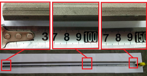
Figure 1 - Overall and partial photos of the workpiece with a thickness of 1500mm
In order to intuitively explain the reasons for the formation of stripes, the molybdenum wire feeding model shown in Figure 2 was established. Figure 2(a) is the theoretical feed path, but when the molybdenum wire vibrates, due to the low rigidity of it, a slight disturbance will deviate from the theoretical feed direction, so the feed does not strictly follow the theoretical straight line direction. Instead, the discharge is oscillated in a predetermined direction, as shown in Figure 2(b), then vibration fringes will be generated on the workpiece surface.
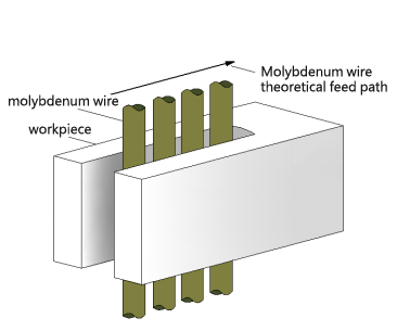
(a) Molybdenum wire theoretical feed path

(b) Feed path when the molybdenum wire vibrates
Figure 2 - Feeding Model of Interpole Molybdenum Wire during Ultra-high Thickness Cutting
2. Internal and external factors affecting cutting stability
EXTERNAL FACTORS:
During ultra-high thickness processing, in order to get a relatively flat surface, the stability of the molybdenum wire between the poles must be maintained. The customary practice is to use new molybdenum wire, new EDM Gel, and use constant tension mechanism, EDM Guide Wheel, and EDM wire guide to improve the stability of molybdenum wire. The EDM wire guide is mainly used to cut off the path of the vibration caused by the runout of the EDM guide wheel and the bearing and the change of the molybdenum wire tension to the processing area, as shown in Figure 3(a). After passing it, the vibration of the molybdenum wire due to the guide wheel and bearing will be greatly attenuated.
INTER FACTORS:
During the ultra-high thickness cutting, the vibration of the molybdenum wire caused by the discharge explosion force in the narrow and long processing area is the internal factor that affects the processing stability. For general EDM Gel, it is impossible to completely fill the narrow and long slit of the workpiece. Even if the slit can be filled, there will be a lot of vaporization under the action of high discharge temperature. Then in the second half of the slit, the EDM Gel will be greatly reduced, or even gone, so it cannot form a better and uniform damping and vibration-absorbing effect on the vibration of the molybdenum wire throughout the slit.

(a) General EDM Gel isn’t full of the slit
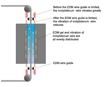
(b) Upgraded EDM Gel is full of slit
Figure 3 - Schematic diagram of vibration of molybdenum wire between electrodes during ultra-high thickness cutting
3. Conditions that guarantee the surface finish of workpiece
a. It must ensure that the slit is evenly filled with EDM Gel so that the vibration of the molybdenum wire can be evenly damped and absorbed in the entire narrow slit, as shown in Figure 3(b). To ensure that the slit is evenly filled with EDM Gel, the following points need to be done. Firstly, EDM Gel needs to have good cooling, washing, and deionization properties, and can be brought into the slit with molybdenum wire; secondly, the discharge gap should be enlarged as much as possible, so that EDM Gel can easily enter the slit, in order to obtain a wider discharge gap, it needs to appropriately increase the conductivity of EDM Gel, the no-load voltage, and the energy.
b. Due to the longer distance for chip removal of corrosion products, even if EDM Gel has filled the narrow and long slit,when cutting ultra-thick workpieces, it is necessary to reduce the vaporization of EDM Gel as much as possible and increase the proportion of high melting point and vaporization point components in EDM Gel to ensure that there is enough chip removal power to take out the erosion products. Figure 4 is a model diagram of the inter-pole state of different EDM Gels.
As shown in Figure 4(a), because of the narrow slit, the amount of general EDM Gel that can enter the slit is relatively small, and it is continuously vaporized in the narrow and long slit, so that it cannot have a damping and vibration-absorbing effect on the molybdenum wire; in addition, the ability to carry discharge erosion particles to discharge the workpiece is greatly reduced, and a large amount of erosion products will accumulate in the lower part of the slit, resulting in unstable processing.
The JR-3A EDM Gel with higher conductivity and added components with high melting point and vaporization point solves this problem in a targeted manner. Since a wider discharge gap can be obtained, the amount of working fluid that enters the slit with the molybdenum wire will increase, so in the narrow and long slit, it can have a good damping and vibration absorption effect on molybdenum wire. In addition, due to the components of high melting point and vaporization point in the working liquid increase, the chip removal power is greatly improved, and the corrosion products can be smoothly discharged from the slit, which further enhances the cutting stability. The schematic diagram between the poles is shown in Figure 4(b).
After the conductivity of EDM Gel increases, the leakage current will increase and consume part of the discharge energy. At the same time, the increase of the discharge gap will also reduce the cutting speed per unit current. However, because cutting stability is a crucial condition to ensure the smoothness of the cutting surface, the pursuit of cutting stability is the most important goal. In addition, the JR-3A EDM Gel can use a larger current for cutting, so the absolute cutting speed of the machine tool is not reduced.
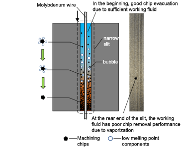
(a) Interpolar state of general EDM Gel and corrosion products carried by it
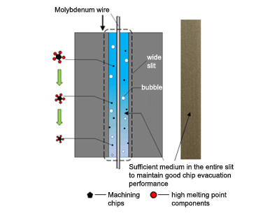
(b) Interpolar state of upgraded EDM Gel and corrosion products carried by it
Figure 4- Interpolar state of different EDM Gel and corrosion products carried by it
c. Appropriately increasing the viscosity ofEDM Gel on the premise of ensuring sufficient cooling, washing and deionization of it can further buffer and dampen the vibration of the molybdenum wire, thereby achieving the purpose of improving the surface finish of the cutting. The most direct way to increase viscosity is to increase the concentration of EDM Gel.
4. Actual processing effect
Figure 5 shows the ultra-thick workpiece cut by the machine tool after using EDM wire guide, constant tension device, and adjusting EDM Gel and other comprehensive measures. It can be seen that the flatness of the cutting surface has been greatly improved.
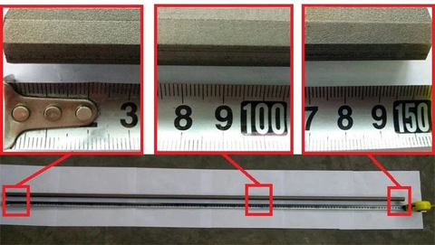
Figure 5 -1500mm workpiece cut by machine tool after comprehensive measures
5. Features and recommended processing parameters upgraded version of working fluid
It should be noted that in some extreme processing situations, such as ultra-high thickness cutting, high-efficiency cutting, etc, although the quality of EDM Gel plays a crucial role, the final process index of cutting is the manifestation of the comprehensive effect and matching of the machine tool, power supply, servo control and working fluid.
In order to ensure long-term and stable cutting under the condition of high cutting energy, the upgraded EDM Gel adopts the following key technologies on the premise of retaining the characteristics of general EDM Gel:
① Cationic micelle protection technology.
Using the directional motion formed by the cationic micelles during processing, which is actively wrapping the molybdenum wire of the negative electrode , it forms a more active wrapping protection effect on the molybdenum wire, makes the protective armor on the surface of it stronger, more reliable and thicker. Therefore, the diameter loss of molybdenum wire is nearly 50% lower than that of general EDM Gel.
② Improve the high melting point and high vaporization point components in the working fluid, and enhance the chip removal power of EDM Gel under high thickness and efficient cutting conditions.
For general EDM cutting: due to the good protection of molybdenum wire, the upgraded EDM Gel is suitable for long-term stable cutting under high current conditions. Users can choose different EDM Gel ratios according to cutting needs.
Wire Guide and Rubber Seal
Vendor:
TAGUTI EDM
CZ140 Wire Guide Wire guide diamond or ruby guide roller for wire cut EDM features with high accuracy of inner hole, mellow and full hole diameter, long service life with manual grinding of inner hole, easy to feed wire smoothly and hard to break....
- from $15.00
- from $15.00
- Unit price
- / per
Vendor:
Sodick
S140D Wire Guide Agie Charmilles & Sodick Wire guide diamond or ruby guide roller for wire cut EDM features with high accuracy of inner hole, mellow and full hole diameter, long service life with manual grinding of inner hole, easy to feed wire smoothly...
- from $18.00
- from $18.00
- Unit price
- / per
Vendor:
Agie Charmilles
Electrode Guide Agie Charmilles Actspark SD1 Wire guide diamond or ruby guide roller for wire cut EDM features with high accuracy of inner hole, mellow and full hole diameter, long service life with manual grinding of inner hole, easy to feed wire smoothly and...
- $18.00
- $18.00
- Unit price
- / per
Vendor:
TAGUTI EDM
S140C Wire guide Wire guide diamond or ruby guide roller for wire cut EDM features with high accuracy of inner hole, mellow and full hole diameter, long service life with manual grinding of inner hole, easy to feed wire smoothly and hard to break. ...
- $15.00
- $15.00
- Unit price
- / per
Vendor:
TAGUTI EDM
Product Specification
TAGUTI Number:Z140
Outer Size:Φ6*Φ8*30mm
Diameter Range:Φ0.30-3.00mm
Outer Case Material:Stainless steel
Inner Core Material:Ceramic
※Special size can be customized should you have the demand!
- $15.00
- $15.00
- Unit price
- / per
Vendor:
TAGUTI EDM
Z140A Wire Guide Wire guide diamond or ruby guide roller for wire cut EDM features with high accuracy of inner hole, mellow and full hole diameter, long service life with manual grinding of inner hole, easy to feed wire smoothly and hard to break....
- $18.00
- $18.00
- Unit price
- / per
Vendor:
TAGUTI EDM
ZZ140 Wire Guide Wire guide diamond or ruby guide roller for wire cut EDM features with high accuracy of inner hole, mellow and full hole diameter, long service life with manual grinding of inner hole, easy to feed wire smoothly and hard to break....
- $15.00
- $15.00
- Unit price
- / per
Vendor:
TAGUTI EDM
Rubber seals
The rubber seals have good elasticity, which are not easy to leak, and have a long service life.
Product Specification
Commodity: Rubber seals
Specification: OD8*6mm
TAGUTI number: E040
Packing quantity: 1 set(10 pcs)
Application: EDM drilling
Category: Seal
- $1.99
- $1.99
- Unit price
- / per
Vendor:
TAGUTI EDM
Rubber Seals The rubber seals have good elasticity, which are not easy to leak, and have a long service life. According to the different outer diameters of brass electrode tubes and copper electrode tubes, we offer 3 types of rubber seals with different inner holes....
- $1.99
- $1.99
- Unit price
- / per
Vendor:
Sodick
Rubber Seal The rubber seals have good elasticity, which are not easy to leak, and have a long service life. According to the different outer diameters of brass electrode tubes and copper electrode tubes, we offer 3 types of rubber seals with different inner...
- $1.99
- $1.99
- Unit price
- / per
Vendor:
TAGUTI EDM
Product Specification
Commodity: Water Stop Column
Specification: OD10*ID3*25mm
Packing quantity: 1 pc
Application: EDM drilling
Category: Seal
- $0.99
- $0.99
- Unit price
- / per
Vendor:
TAGUTI EDM
Drill Chuck The Drill chucks are used to clamp brass electrode tubes and copper electrode tubes. They have the characteristics of good concentricity, firm clamping, long service life, and easy replacement. Type Clamping Range Taper Hole At End Outer Diamrter Length EDM Drill Chuck Ø 0.2 - Ø 4.0mm...
- from $6.99
- from $6.99
- Unit price
- / per
Vendor:
TAGUTI EDM
Drill chuck The Drill chucks are used to clamp brass electrode tubes and copper electrode tubes. They have the characteristics of good concentricity, firm clamping, long service life, and easy replacement. Type Clamping Range Taper Hole At End Outer Diamrter Length Precision Drilling Chuck Ø 0.0 - Ø 3.0mm...
- $49.99
- $49.99
- Unit price
- / per
Vendor:
TAGUTI EDM
The Nuts for EDM Drill Chuck are used to fix the chuck of the small hole drilling machine. The tapered shaft core is easy to install and the connection is firm.
Product Specification
Outer Size: ф 24.0*M14.0*22.0mm
- $4.99
- $4.99
- Unit price
- / per
Vendor:
TAGUTI EDM
The Nuts for EDM Drill Chuck are used to fix the chuck of the small hole drilling machine. The tapered shaft core is easy to install and the connection is firm.
Product Specification
Outer Size: ф 32.0*ф22.0*M16.0*13.0mm
- $6.99
- $6.99
- Unit price
- / per
Tags:
