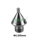
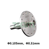
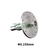
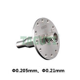
Mitsubishi LS-WEDM wear parts and maintenance guide
As a precision machining equipment, lower speed wire cutting EDM machine tools play an important role in mold manufacturing, precision parts processing and other fields. Mitsubishi wire-cutting machine tools are known for their high precision and stability, but during long-term use, some parts are prone to wear due to frequent operation or environmental factors, which in turn affects processing efficiency and precision. We combine the characteristics of the equipment and explore the details to help users master maintenance skills more comprehensively.
1. Analysis of types of wear parts and common problems
The wear parts of Mitsubishi wire cutting machine tools are mainly concentrated in the mechanical transmission system, electrical control system and working fluid circulation system. The following are key wear parts and their typical problems:
1.1 Eletrode wire (Brass wire)
The problem of wire breakage: LS-EDM wire cutting uses high-precision electrode wire (such as brass wire, zinc coated wire, etc.). Due to continuous discharge machining, the surface of wire is prone to tiny cracks, oxidation or fatigue damage. Wire breakage is often near the power feed contact, the wire guide or the processing area, which may be caused by the following factors:
Too much or too little tension: Abnormal tension will aggravate the vibration or relaxation of the electrode wire, causing the cutting track to deviate or scrape the wire;
Wear of power feed contact: Grooves or carbon deposits on the surface of the power feed contact will hinder the smooth passage of the electrode wire and cause local friction;
Poor quality of working fluid: Impurities in the working fluid (such as metal particles, high ion concentration) will affect the conductivity of the machining fluid and the stability of electrical discharge machining;
Improper processing parameters: such as excessive processing current and too fast cutting speed, which may cause the electrode wire to overheat and burn out.
1.2 Power feed contact
Material and function:
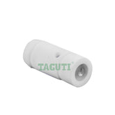
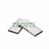
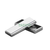
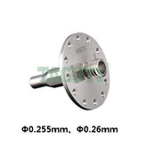
The power feed contact is usually made of cemented carbide, responsible for the stable connection between the brass wire and the power supply, and withstands high-frequency discharge. Its wear is manifested as surface grooves, carbon deposits, cracks or peeling of the conductive coating.
Common problems:
Carbon deposition leads to poor conductivity, frequent wire breakage or reduced processing efficiency;
Uneven surface wear leads to inaccurate electrode wire positioning, affecting cutting accuracy;
The cooling water channel is blocked, causing the power feed contact to overheat locally and accelerate aging.
1.3 Wire guide components (guide wheels, bearings, etc.)
Composition: The guide wheel (such as ceramic guide wheel, polyurethane rubber tension wheel), bearing, guide arm and other components constitute the support and guide system of the brass wire. Continuous friction, foreign matter embedded or insufficient lubrication can easily cause the following problems:
Wear of the guide wheel causes the electrode wire to vibrate more and the finish of the machined surface is reduced.
Bearing seizure or wear increases the resistance of brass wire movement and increases the risk of wire breakage;
The wire guide arm is loosely positioned, causing the brass wire to deviate and the processing size error to exceed the tolerance;
Daily inspection: Regularly observe the surface of the guide wheel to see if there are grooves or vibrations.
1.4 Nozzle and flushing system
Functions: The nozzle is responsible for spraying the working fluid (deionized water + additives) at high pressure into the processing area to cool the brass wire, remove chips, and stabilize the discharge channel. Common faults include:
Nozzle blockage: Chips or impurities accumulate, resulting in insufficient flushing pressure and increased temperature in the processing area;
Nozzle damage: Collision or high-pressure impact causes the nozzle to deform, affecting the spray angle and flow rate;
Fluctuation of water spray pressure: Water pump failure or pipeline leakage reduces processing stability;
Optimization suggestion: Select inner diameter of the nozzle (such as φ4.0mm, φ6.0mm, etc.) according to the material, thickness and slope of the workpiece, and monitor in real time based on the jet pressure sensor.
1.5 Power modules and electrical components
High-voltage component risks: High-voltage capacitors, IGBT modules, voltage regulators, etc. in the power module are prone to aging, breakdown, or overheating due to long-term high-load operation. For example, capacitor expansion and leakage will cause unstable output voltage, which will directly affect the use of machine tools.
Control component problems: Relays, terminals, circuit boards, etc. in the controller may have poor contact or short circuits due to dust accumulation, high humidity or vibration, causing system errors.
Preventive measures: Regularly clean the dust on the air filter of the electrical cabinet, check whether the fan is operating normally, and clean the dust on the surface of the circuit board in time.
1.6 Sensors and measuring elements
Precision assurance components: position sensors (such as grating rulers, encoders), current/voltage monitoring components, etc., if not calibrated regularly, may cause:
Accumulation of displacement measurement errors causes workpiece size deviation
Discharge parameter monitoring is inaccurate and processing strategies cannot be adjusted in time;
Calibration method: Use standard gauge blocks or laser interferometer to calibrate the grating ruler to ensure the error is less than or equal to 0.003mm per full range.
2. System maintenance strategy
Scientific maintenance is the key to extending the life of machine tools and ensuring processing quality. The following are maintenance steps and techniques, covering daily, weekly, monthly and annual tasks.
2.1 Daily maintenance of mechanical parts
Electrode wire management
Daily inspection: Before starting the machine, check the electrode wire surface for burrs, oxidation discoloration, or diameter changes (the standard diameter is usually ±0.002mm)
Tension adjustment: Use a tension meter to calibrate regularly (recommended tension 1.5-2.0N) to avoid wire breakage or cutting deviation due to tension fluctuations.
Power feed contact maintenance
Weekly cleaning: Use a special brass wire brush or alcohol to wipe the surface carbon powder, and be careful not to damage the power feed contact coating.
Rotate or replace: When the depth of the groove on the surface of the power feed contact exceeds 0.2mm, it needs to be rotated or moved before continuing to use.
Cooling optimization: Check the cooling water circuit pressure (recommended 0.2-0.3MPa) to prevent overheating of the power feed contact due to insufficient cooling.
Guide wire system maintenance
Disassemble the guide wheel assembly every month: use compressed air to clean the waste wire in the gap between the bearing and the guide wheel, and add special grease.
2.2 Optimization of working fluid system
Water quality control
Daily monitoring: Use a conductivity meter to test deionized water (≤10μS/cm), and replace the resin if it exceeds the standard;
Regular replacement: Regularly replace the working fluid to prevent microbial growth or accumulation of ion concentration;
Filtration system maintenance: clean the water tank sediment every 4 weeks and check the filter pressure difference (replace the filter if it exceeds 0.2MPa).
Flushing pressure regulation
Adjust the nozzle distance according to the thickness of the workpiece (for example: for veneer processing of thin workpieces, keep a 0.5-1mm gap for thick workpieces);
Adjust the pressure regulating valve to ensure that the pressure difference between the upper and lower nozzles is less than or equal to 0.05MPa to avoid pressure imbalance in the processing area.
2.3 Preventive maintenance of electrical systems
Power module check
Clean the dust in the power cabinet and the scale on the heat sink every quarter (use a vacuum cleaner or compressed air)
Check the appearance of the discharged capacitor. If it is found to be swollen, leaking or the electrolyte is discolored, replace it immediately.
Use an oscilloscope to regularly check the output voltage waveform to ensure there is no distortion or noise.
Controller and sensor calibration
Conduct a comprehensive inspection of the controller every year: tighten the wiring terminals, test the response time of each relay;
Sensor calibration: Perform in a constant temperature environment (20±2℃) to avoid temperature drift affecting accuracy.
2.5 Environment and operating specifications
Machine tools installation environment
Dust prevention measures: Install air filters to prevent metal dust from entering the transmission parts;
Vibration isolation: Use anti-vibration pads on the machine tool foundation, away from vibration sources such as punch presses and machining centers;
Temperature and humidity control: The ambient temperature is maintained at 18-25°C and the humidity is less than or equal to 70% to prevent rusting of electrical components or condensation on circuit boards.
Operating instructions
Workpiece clamping: Use special clamps to ensure that the workpiece is insulated from the work surface to avoid short circuits.
Parameter setting: It is strictly forbidden to modify the processing parameters set by the original factory (such as pulse frequency, current value) without authorization.
Emergency shutdown process: When an abnormality occurs, turn off the high voltage power supply first and then troubleshoot the fault to avoid arc damage to machine tool components.
3. Fault response and handling
3.1 Fast fault response and diagnosis
Broken wire processing process
Stop the machine immediately and check the location of the broken wire (power feed contact, guide wheel, processing area);
Use the broken wire retrieval function to retract the electrode wire to the vicinity of the breakpoint and manually clean up the broken wire residue;
Analyze the cause of wire breakage (such as tension, power feed contact, water quality), adjust parameters and then process again
Common troubleshooting table
Processing speed drops suddenly: Check nozzle blockage, working fluid conductivity, power module output voltage;
Frequent alarms: Check the machine log to locate the error code (such as E-01: abnormal tension, E-03: water quality exceeds the standard);
Poor surface roughness: adjust the flushing pressure, optimize the discharge parameters or replace the guide wheel.
3.2 Preventive Maintenance Plan (Example)
Monthly tasks
Clean the wire guide, replace the working fluid, and calibrate the X and Y axis sensors;
Check the heat sink of the power module and tighten the wiring terminals of the electrical cabinet.
Quarterly tasks
Disassemble and check the lubrication of the guide wheel bearing and replace the worn bearing;
Test the power module capacitor capacity and replace components that have exceeded their service life.
Yearly tasks
Comprehensive inspection of mechanical accuracy (such as verticality and parallelism calibration);
Update the lubrication system oil circuit and replace aging seals;
Electrical system aging assessment and development of upgrade and renovation plans.
3.3 Data management and efficiency improvement
Logging and analysis
Use the machine's own data acquisition system to record processing parameters and component life data;
Analyze the electrode wire replacement cycle and wire breakage rate trend through SPC (Statistical Process Control) to optimize maintenance intervals;
Long-term goals: Achieve "zero failure" operation through standardized maintenance processes and data-driven decision-making, and increase the machine tool MTBF (mean time between failures) to more than 2,000 hours.
4. Special parts maintenance tips and precautions
4.1 Precautions for replacing precision parts
Replacement of power feed contact: high-quality accessories must be used to avoid misalignment during installation that may cause scratches on the electrode wire.
Bearing replacement: Use special tools to disassemble and avoid knocking to damage the guide wheel or shaft core.
4.2 Seasonal and environmental adaptation maintenance
High temperature season: Increase the frequency of checking the cooling fan of the power module to prevent overheating;
Cold regions: Preheat the hydraulic system before starting the machine tool in winter to avoid transmission jamming caused by excessive oil viscosity.
5. Conclusion
The high performance of Mitsubishi wire-cut machine tools depends on the coordinated operation and scientific maintenance of precision components. By systematically identifying wearing parts, implementing graded maintenance strategies, and establishing a data-based management system, users can not only reduce maintenance costs and extend machine tool life, but also stabilize machining accuracy and improve production efficiency. Users dynamically adjust maintenance plans based on their own production environment, maintain technical linkage with equipment suppliers, regularly participate in training, master the latest maintenance technology, ensure that machine tools are always in the best working condition, and provide reliable protection for precision manufacturing.
Mitsubishi Parts
- $71.50
- $71.50
- Unit price
- / per
- $65.50
- $65.50
- Unit price
- / per
- $59.50
- $59.50
- Unit price
- / per
- $156.50
- $156.50
- Unit price
- / per
- $143.50
- $143.50
- Unit price
- / per
- $129.50
- $129.50
- Unit price
- / per
- $71.50
- $71.50
- Unit price
- / per
- $65.50
- $65.50
- Unit price
- / per
- $59.50
- $59.50
- Unit price
- / per
- $63.00
- $63.00
- Unit price
- / per
- $58.00
- $58.00
- Unit price
- / per
- $52.50
- $52.50
- Unit price
- / per
- $52.50
- $52.50
- Unit price
- / per
- $63.00
- $63.00
- Unit price
- / per
- $58.00
- $58.00
- Unit price
- / per
